Welcome Ducks! In this blog, we’ll explore the intricacies of creating dynamic blocks from scratch in AutoCAD. We’ll cover adding editable attributes and working with the most common block parameters. To help you follow along, I’ll break down the steps and provide guidance on how to create a versatile 24 by 48 panel block that includes stretchable features and a finished tag.
Starting with the Basics
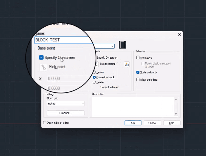
To kick things off, let’s create a simple 24 by 48 rectangle and convert it into a block.
Important tip: always ensure that the “specify on the screen” option is checked. Select your base block. In our example, this block will represent the elevation view of a well tunnel, so it needs to be stretchable and include a finished deck.
Adding an Editable Attribute
We’ll use the Define Attribute tool to add our finish tag. Begin by entering the block editor. You can do this by right-clicking your block and selecting the block editor option, or by typing “bedit” into the command prompt.
Once inside the block editor, look for the Attribute Definition command in the new blue-highlighted tab on your ribbon. Click it to open a window where you can set various properties for your new attribute, from visibility to multiple-line filling modes. Make sure the desired options are checked and start filling in your attribute tag.
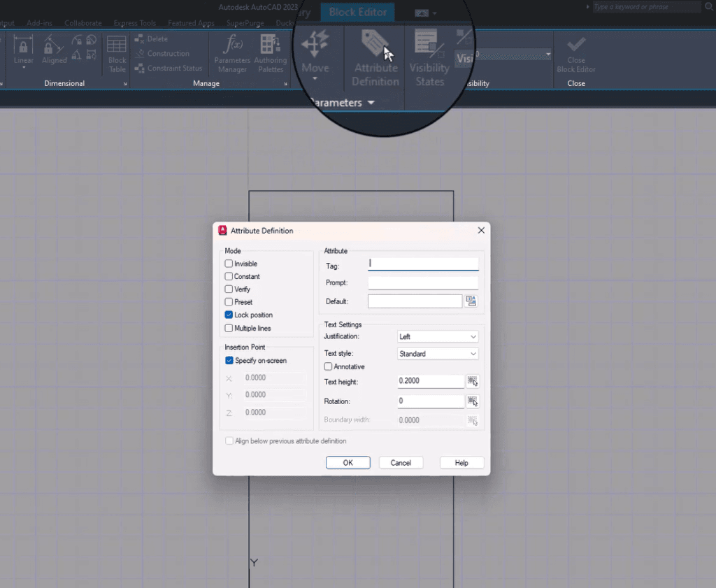
Note: AutoCAD does not allow spaces in attribute fields, so be sure to use underscores.
Use the Prompt field to guide users on filling out the attribute and provide a default value for new blocks. We will keep Text Justification, Text Style, and the Annotative option as default settings. Set the Text Height to 1.5 units, click OK, and pick your finish tag’s insertion point.
Finalizing and Syncing Your Block
After setting up your attribute, close the block editor, save changes, and run the “ATT Sync” command to see the updates. Select your block to confirm the changes, allowing you to modify your finished tag by double-clicking.
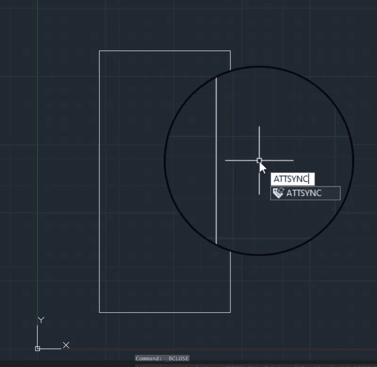
Important: Remember to apply the “attsync” command anytime you modify an attribute.
Working with Parameters and Actions
To create blocks that switch between views or modify geometry with grip clicks, understanding parameters and actions is crucial. Back in the block editor, if the block authoring palette does not appear by default, activate it via the corresponding button.
For now, we will focus on parameters and actions. AutoCAD parameters hold values such as lengths or visibility states, while actions change these values based on user inputs or rules.
Adding a Basic Parameter
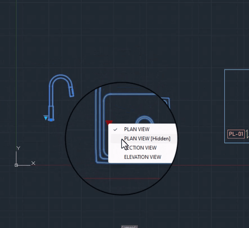
Add the first parameter by clicking on “possibility” and selecting a point for the group to be shown. This basic parameter has a single action. You will see it enabled on your ribbon once you click for the grid point. Manage your visibility states from this point, adding, renaming, deleting, or reordering them as needed.
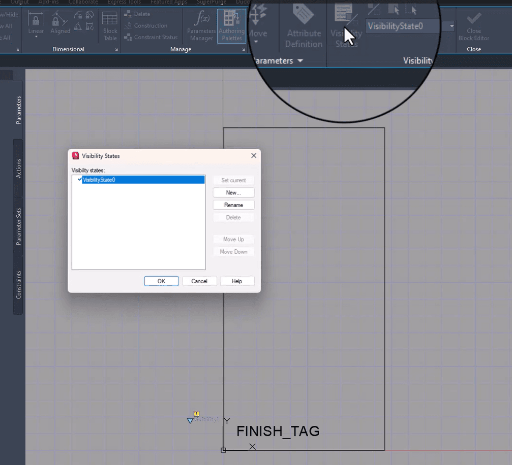
Rename your default state to “finish tag” and add a new state, “no tag.” Close the window, switch between states, and hide objects as necessary. To bring back hidden objects or show others from different states, use the “make visible” option.
Including Stretch Grips
To add stretch grips, we will add a linear parameter to the distance we want to modify. Select start and end points, then press enter. This parameter requires an action to function, so go to the actions tab and pick the stretch action. Select your parameter and click near the specified grip.
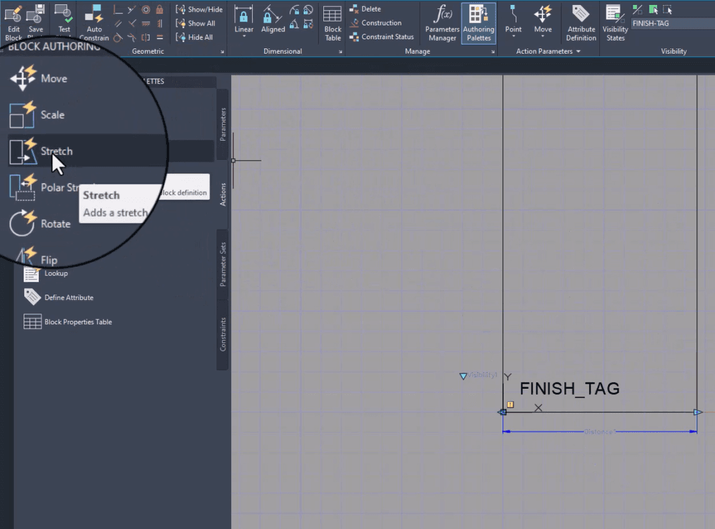
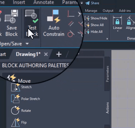
Similar to the stretch command, a selection frame covers only the groups you want to be stretched. After selecting the objects, press enter and test your block using the test block option.
Adjusting Parameters and Testing
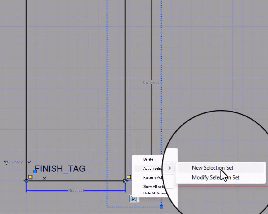
If your height parameter isn’t included in the width parameter selection set, resolve this by modifying the selection set. Right-click next to the width parameter, go to action selection set, and modify accordingly.
Assigning names to parameters makes them visible in the block properties tab. Set names to parameters like “panel width” and specify minimum and maximum distances (e.g., 48 inches for width and 96 inches for height).
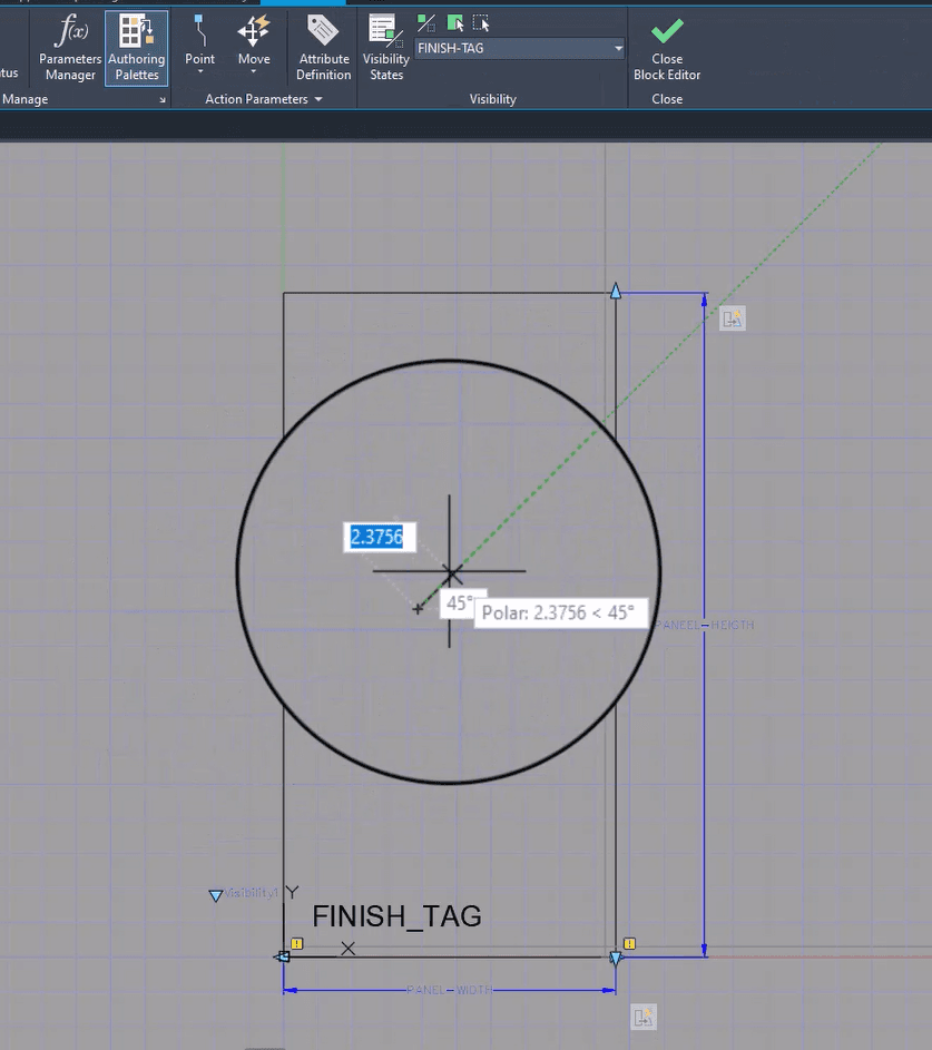
Adding the Grain Direction Symbol
Include a grain direction symbol, ensuring it remains centered regardless of stretch actions. By removing the grain direction from existing actions and adding new ones with a distance multiplier set to 0.5, the symbol maintains its position accurately.
Final Testing
Use the move action to set the grain direction for the height parameter.
Afterward, we conduct final testing to ensure everything works correctly!
Thank you for following along, and have a great day creating dynamic blocks in AutoCAD!

Enrique Arauz
Training Coordinator